14.1 INTRODUCTION
The STLINE streamline model provides an efficient and economical means of computing particle-movement trajectories, distances and times. The model uses a discrete steady-state velocity field or a series of velocity fields created from a previous flow simulation. After establishing initial particle locations, the program tracks the movement of individual particles through time. The trajectory (or streamline) of each particle may be displayed as a trace of discrete points as viewed in each of three orthogonal planes within an assumed Cartesian coordinate system. Any consistent set of units may be used.
The program is written with a flexible input format. Grid block dimensions, velocities and porosities are read as unformatted records from a previous flow simulation using SWIFT/486 (Reeves et al., 1986a and b; Ward et al., 1993).
14.2 STREAMLINE EQUATIONS
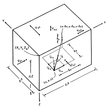
The grid is assumed to consist of a set of rectangular parallel pipes, or grid blocks, like the one shown in Figure 1. The SWIFT code calculates potentials at grid-block centers and then differences them to obtain interstitial fluid velocities at the grid-block edges. Thus, only the centers and edges of the individual cells are of concern. For particle tracking, however, intra-cell translations must be determined, and it is convenient to supplement the system, or global coordinates (X,Y,Z) with local grid-block coordinates (x,y,z) (see Figure 14.1).
Because velocities are known only at
the grid-block edges, interpolation is used within individual cells. The
program uses linear interpolation. Thus, for any local position (x,y,z),
the x-component of velocity is given by
![]()
where
![]()
Here, and throughout this section, only relations for the x component are presented since comparable relations for the y and z components may be obtained easily by analogy. In Eqs. (1) and (2), V1x and V2x denote edge velocities and DX denotes a grid-block width, as shown in Figure 14.1.
The distance travelled (dx, dy, dz) in the time step dt may be determined analytically by integrating the equation
![]()
where
![]()
Solving Eqs. (4) and (5) for Dx yields the result
![]()
From the coordinate increments, as determined from equations of the form of Eq. (6), the incremental path length is obtained from
![]()
In applying Eq. (6) and its counterparts in the y and z directions, two inaccuracies can occur. One of them may be described as an inter-cell error, which results from a particle crossing a cell boundary. In such an event, the particle velocity is determined by extrapolation of Eqs. (1) and (2) for the source cell rather than using velocities appropriate for the receiver cell. To minimize such errors, it is necessary that
![]()
where the angle brackets denote the
grid-cell average
![]()
The other error may be described as
an intra-cell error resulting from the approximation of Eq. (4). There
the error term of least order is given by
![]()
assuming a linear variation in velocities within the grid block. Both Eqs. (8) and (10) imply a limitation on the time step. Analytical application of these equations is somewhat difficult due to their grid-cell dependence and the uncertainty of the particle paths. Practical application of the error relations of Eqs. (7) and (9), however, may be implemented easily by making a very rough estimate of the time step from Eq. (8).
In order to determine particle trajectories
and, hence, the streamlines of the flow field, the STLINE code accumulates
global position coordinates for each particle using the increments as defined
in Eq. (6). Adding a subscript to indicate particle identity and a superscript
to indicate the time step, the resulting coordinate may be expressed as
![]()
with comparable relations for
Ypn and Zpn.
For each trajectory, the program also accumulates a global path length
from the path length increments defined in Eq. (7):
![]()
14.3 COMPUTER IMPLEMENTATION
The STLINE program consists of a main program and several subroutines. The input consists of input/output control parameters; grid-structure values; flow information, i.e., Darcy velocities and porosities; initial particle positions; time-increment variables; and plotting specifications. The output consists of three-dimensional arrays of Darcy velocities, and porosities in one file and files of particle trajectories, or streamlines.
Initial particle locations (X , Y , Z ) within the global grid system are specified in input record R11 (see next section) by real numbers of the form (I.i, J.j, K.k). Integers I, J and K denote the grid block, and the remaining fractions i, j, and k correspond to the fractional distance across that grid block in the x, y, and z directions, respectively. An example is the centroid of the first grid-block (1,1,1), which is specified with the coordinates (1.5, 1.5, 1.5).
The tracking of the individual particles as they move from their initial locations is accomplished by means of the five parameters TMAX, TOLXY, TOLZ, FRACDXY, and FRACDZ, which are input on record R5. These parameters determine the automatic time stepping for each particle with special attention for horizontal and vertical movement. The parameter TMAX is the total desired simulation time. Particles will be translated up to a value TMAX unless limited by the maximum number of time steps. The automatic time steps are controlled by the allowable fractional block distance. The parameters FRACDXY and FRACDZ define the fractional (i.e., distance normalized with respect to block increment dimension) movement desired. The fractional movement in turn is used to determine the desired time step. This scheme allows for automatic updating of the time step as a particle experiences changes in the velocity field from block to block. The code seeks to provide stability in Courant ratio (Vdt/DX).
Streamlines are calculated with individual time stepping. The time step is chosen based on the minimum travel time for horizontal (x or y) and vertical (z) directions. The control parameters FRACDXY and FRACDZ may be tuned to best fit a streamline. A zero value can be entered for FRACDZ in order to skip vertical projection calculations. This would be appropriate for many three-dimensional applications where horizontal translation control the time step criteria. In many hydrologic applications, FRACDXY will be most useful.
Streamlines which pass through perimeter or boundary grid blocks will be sensitive, of course, to the boundary velocities. Unfortunately, such velocities typically are not defined by block-centered finite-difference codes, for which STLINE has been designed. Consequently, option parameters IBCX, IBCY, and IBCZ have been provided in input record R6. These parameters permit one either to specify a no-flow boundary or to set the velocity to that of the adjacent block edge for each of the three coordinate directions i.e., if the flow model has a discharge boundary such as a river or prescribed head boundary.
Transient velocity fields may be used by creating a series of velocity records with SWIFT-98. Values are written to the file each time they are printed as controlled by variable IIPRT on Record R2-13 of the SWIFT-98 data file. The transient velocity fields are read (variable ITRANS, Record R2) and linear interpolation is used between epocs. If the first velocity is written at times other than zero, the first velocity field is held constant between time zero and when the first velocity is written. Thereafter interpolation between two velocity fields is performed.
The final topic to be discussed in this section is, appropriately, that of termination of the particle tracking. As indicated above, a maximum simulation time is specified within the input. However, the code is made more efficient by three additional termination criteria. Particle tracking is terminated whenever one (or more) of the following conditions is met:
2. The maximum number of allowable calculation time steps (ITMAX, Record R2) is exceeded;
3. All of the particles have exited from the flow field i.e., at a river or prescribed head boundary; and
4. The minimum bound, or tolerance (TOLXY or TOLZ, Record R5), on particle movement is reached by all of the particles.
14.4 DATA FILES
The STLINE program requires:
1. Input data file to define the particle location and print options.
2. Velocity file from a previous SWIFT/486 simulation.
3. Screen input to define the above files.
RUN77 STLINE INSTL SW_RUN1
where:
SW_RUN1.VL is the output velocity from the SWIFT/486 simulation using SW_RUN1.DAT.
2. SURFER7 boundary line files where line segments are concatenated, one boundary line for each particle.
3. MODPATH pathline file, similar to boundary line file, but formatted the same as output created by MODPATH (Pollock, 1989). MODPATH is the pathline post processor for MODFLOW (McDonald and Harbaugh, 1988).
4. SURFER7 posting file to allow posting of symbols or time display in conjunction with the boundary line file.
| UNIT | FUNCTION | FILE SUFFIX |
| * | Screen Display | --- |
| 5 | Input File | .DAT |
| 6 | Output (80 col.) Listing | .OUT |
| 7 | SWIFT-98 Input Velocity (Binary) | .VL |
| 8 | SURFER Boundary Line | .BLN |
| 9 | MODPATH Pathline | .TRK |
| 10 | SURFER Posting Data | .DPS |
14.4.1 Input Data
The following data define the parameters used in the particle tracking program. This includes the control variables, the simulation option and initial particle location are defined. This is read from UNIT 5 and is an ASCII formatted file.
RECORD R1 (A65) COMMENTS
LIST: TITLE
RECORD R2 (8I5) CONTROL PARAMETERS
LIST: NX, NY, NZ, NP, NTM, ITRANS, IDBUG, IREVS
NP Number of particles to be tracked (col. 16-20).
ITRANS Index for transient velocity
field input (col. 26-30):
1=Transient velocity
IDBUG Index for diagnostic output control
(col. 31-35):
1=Partial diagnostic
2=Complete diagnostic
1=Reverse tracking
RECORD R3 (12I5) PRINT OPTIONS
LIST: IDX, IVX, IVY, IVZ, IPHI, KPNT, ISUR, IELEV, KSUR, KPST, IMOD, KMOD
1 = Print
n = every n'th time step
KPNT Frequency control parameter for printing (.OUT) particle locations at the end of each timestep (col. 26-30). [A zero or one means every time step]
1=X-Y coordinates are listed
2=Y-Z coordinates are listed
3=X-Z coordinates are listed
1 = Z is in depth
RECORD R4 (3E10.0) INITIAL LOCATION
LIST: (XI(I), YI(I), ZI(I), I = 1, NP)
(1.0, 1.0, 1.0) is a top outside corner of the system
RECORD R5 (7E10.0) TIME STEP CONTROL
LIST: TMAX, TOLXY, TOLZ, FRACDXY, FRACDZ, TSCLSR, HDAT
TOLXY Minimum tolerance of particle movement in the x or y direction (Default = 0.005). [Tolerance is defined as the smallest allowable coordinate change, relative to the local block dimension. To terminate calculations sooner, enter a larger value. To allow more or continued calculations enter a smaller value. In sink blocks, a particle may overshoot the "exit" if given an inappropriate value.] (col. 11-20).
TOLZ Minimum tolerance of particle movement in the z-direction (col. 21-30).
FRACDXY Fractional block distance (fraction
of DX or DY)
allowed in either the x or y direction per time increment
(col. 31-40). [Values range from 1x10-20 to 0.5, typically 0.05]
FRACDZ Fractional block distance allowed
(fraction of DZ) in
the z-direction per time increment (col. 41-50). Enter a zero to force
horizontal FRACDXY control. [Values range from 1x10-20 to 0.5,
typically 0.05]
TSCLSR Scale factor for the printed values of time on output files (col. 51-60). [For example to list values in years, enter 0.0239 (1/365) to convert SWIFT output in days]
HDAT Value to override HDATUM in SWIFT velocity file (col. 61-70). Enter a zero to use the SWIFT value directly.
RECORD R6 (6I5) BOUNDARY VELOCITY
LIST: IBCX1, IBCX2, IBCY1, IBCY2, IBCZ1, IBCZ2
IBCY1, IBCY2, conditions on all sides of system in each
IBCZ1, IBCZ2 coordinate direction (col. 1-5, 6-10, 11-15).
1=Adjacent block velocities in the specified
14.4.2 Velocity File
The velocity file from the execution of the SWIFT-98 code is an unformatted file containing the grid, the components of velocity and the value of time.
RECORD V1 (Unformatted) VERSION
LIST: NUM
LIST: HDATUM
RECORD V3 (Unformatted) GRID
LIST: NXX, NYY, (DX(I), I=1, NXX), (DY(J), J=1, NYY)
DX, DY Arrays of grid-block increments for x and y coordinates (Real*8).
RECORD V4 (Unformatted) DEPTH
LIST: (H(M), M=1, NB)
RECORD V5 (Unformatted) THICKNESS
LIST: (DZ(M), M=1, NB)
RECORD V6 (Unformatted) PORE VOLUME
LIST: (PHI(M), M=1, NB)
RECORD V7 (Unformatted) VELOCITY
LIST: (UX(M), M=1, NB), (UY(M), M=1, NB), (UZ(M), M=1, NB)
RECORD V8 (Unformatted) PRESSURE
LIST: (P(M), M=1, NB)
RECORD V9 (Unformatted) FLUID DENSITY
LIST: (BW(M), M=1, NB)
RECORD V10 (Unformatted) TIME
LIST: RDTIME
The boundary line file (with .BLN extension) format is designed for direct input into SURFER as follows:
NPTSI ZERO
X(1) Y(1)
X(2) Y(2)
X(3) Y(3)
. .
. .
X(NPTS1) Y(NPTS1)
NPTS2 ZERO
X(1) Y(1)
X(2) Y(2)
X(3) Y(3)
. .
. .
X(NPTS2) Y(NPTS2)
etc.
where NPTS1 is the number of points to define the first particle (i.e., particle A). Zero has a value of 0. The second particle (i.e., particle B) follows directly. There is one set of paired vectors for each of the particles. Because STLINE is three-dimensional and SURFER? is two-dimensional, the user must select the orientation for the SURFER? boundary line file. On Record R3, variable ISUR in the STLINE input control file, the user identifies the orientation of slice as:
2 for Y-Z plane,
3 for X-Z plane.
Also on Record R3, variable IELEV, the user selects the SURFER? orientation for Z as follows:
1 for depth.
14.4.4 Pathline File
The pathline file (with .TRK extension) for defined by MODPATH (Pollock, 1989) contains the following:
| 1. | Particle index number, (col. 1-15) |
| 2. | Global coordinate in the x-direction, (col. 16-35) |
| 3. | Global coordinate in the y-direction, (col. 37-56) |
| 4. | Local coordinate in the z-direction within the cell, (col. 58-77) |
| 5. | Global coordinate in the z-direction, (col. 79-98) |
| 6. | Cumulative travel time, (col. 100-119) |
| 7. | J index of cell containing the point, (col 121-123) |
| 8. | I index of cell containing the point, (col 125-127) |
| 9. | K index of cell containing the point (col. 129-131). |
The output is ASCII using the format (Fortran):
FORMAT (I15,1X,5(E20.12,1X),2(I3,1X),I3).
Note that in the MODPATH convention J refer the column or the x-direction in SWIFT and I refers to the y-direction. Other existing software used to present MODPATH output may then be used to display pathlines from STLINE.
14.4.5 Posting File
The SURFER posting file (with .DPS extension) is an ASCII file contains:
X(1) Y(1) T(1) ALF(1) P(1)
X(2) Y(2) T(2) ALF(2) P(2)
X(3) Y(3) T(3) ALF(3) P(3)
. . . .
. . . .
X(N) Y(N) T(N) ALF(N) P(N)
where: X() is the first ordinate,
Y() is the second ordinate,
T() is the elapsed travel time,
ALF() is the velocity vector angle, measured counterclockwise relative to the x-axis, and
P() is the one character identification, i.e., A, B, C etc.
There are N records depending on the number of time steps for each particle and the frequency of writing (Record R3, variable KPST on the control input file). It is recommended that the value of KPST be a multiple of KSUR. This would result in selecting posting of the symbol or value of time along each of the path lines.
14.5 VERIFICATION PROBLEM
In order to illustrate the use of the streamline program, the problem of an injection well in a uniform flow field is presented. The flow field is generated by a steady-state flow simulation using SWIFT-98, and then several streamlines are generated via the particle-tracking method of STLINE. In addition, a comparison is made between the numerical model and analytic results. The sample problem constitutes a verification of the SWIFT-STLINE combination.
14.5.1 Description of the Problem
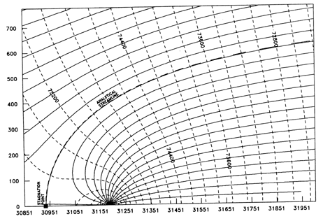
Two of the most important features
of the problem of steady-state injection into a uniform flow field are:
(1) the existence of a groundwater divide which separates aquifer fluid
from injected fluid; and (2) the existence of a stagnation point. Figure
14-2 shows this point for the sample problem under consideration here.
Also, the analytic streamline differs only insignificantly from the groundwater
divide.
These two points may be examined more carefully by considering the analytic solution. Using the notation of Bear (1979, p. 367), this solution may be written in two different forms. First, the piezometric head is given by:
![]()
and secondly, the stream function is given by:
![]()
where:
X = stream function,
qo = ambient Darcy velocity (specific discharge),
K = hydraulic conductivity,
B = aquifer thickness, and
Qw = flow rate (Qw > 0 for injection).
The second equation is more important because constant values of the stream function characterize different streamlines.
The groundwater divide is defined by Eq. (14) with the conditions y ? 0 and tan-1 (y/x) 6 p, as discussed by Bear (1972, p. 324). The resulting equation for the divide streamline is:
![]()
where the signs denote the two branches for y < 0 and y > 0. This curve has the asymptotes:
![]()
The second noteworthy feature of the
analysis is the existence of a stagnation point. Equation (15) is undefined
for y=0. However, the abscissa of this point may be obtained through a
limiting process, and is given by
![]()
The point (xs, 0) represents that point at which the flow diverges at right angles to the x axis. This is therefore a null point for which there is not flow, i.e., a point of stagnation.
14.5.2 Input Data
The hydrological data for the sample
problem is shown in Table 14-2. In addition, grid information is required
by both SWIFT and STLINE. Fine gridding is used in the vicinity of the
well in order to resolve numerically the logarithmic behavior of the fluid
pressure, Eq. (13). Increments are chosen to vary from 5 m to 10,000 m
in both x and y directions as they emanate from the well, as may be inferred
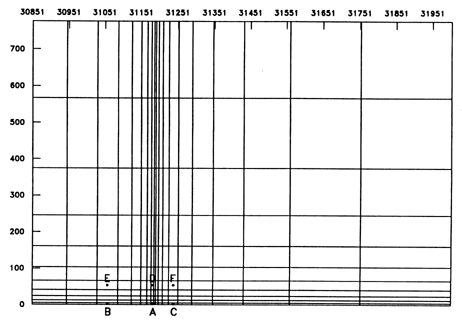
from the limited region shown in Figure 14-3 and Table 14-3. Numerical
streamlines are quite sensitive to the width of the system Ly.
For the analytical model, an infinite system is used, whereas for the numerical
model, a finite system is used of necessity. For comparison with analytic
results, this width is:
![]()
Equation (18) shows the system width (for the numerical simulation) in terms of a fundamental unit of the physical system, namely the asymptote of the groundwater divide, Eq. (16).
The initial particle locations are specified in Card R4. As indicated, STLINE uses the representation M.m for definition of initial coordinates where M is the value of the block index I, J, or K, and m is the fractional distance across the block, in the direction of increasing M. Initial locations are shown in Figure 14-3. They are also given in STLINE and SWIFT coordinates in Table 14-2.
14.5.3 Results
Results of the sample problem are given in Figure 14-4. Six streamlines are shown using the SURFER output of STLINE. As
| Parameter | Value |
| Ambient Darcy Velocity | 1.5 x 10⁻⁸ m/s |
| Hydraulic Conductivity | 4.0 x 10⁻⁶ m/s |
| Porosity | 0.1 |
| Aquifer Thickness | 125 m |
| Injection Rate | 1.5 x 10⁻³ m3/s |
|
|
|
|
|
|
|
31,183 | 2.5 |
|
|
|
31,059 | 2.5 |
|
|
|
31,240 | 2.5 |
|
|
|
31,183 | 53.3 |
|
|
|
31,059 | 53.3 |
|
|
|
31,240 | 53.3 |
|
| WELL | 31,189 | 0.0 |
|
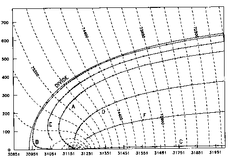
shown, there is a small discrepancy
between numeric and analytic data. This circumstance could result from
a difference in the treatment of the injection well. For the
analytic model, this well is located
precisely at one point. However, for the numeric model, the injection rate
is spread uniformly over one 5x5 m grid block. (For pictorial purposes,
only the well is located at the grid-block centroid in Figure 14-3.) A
more likely source of the discrepancy, however, is the total region size,
particularly in the lateral y direction. For the analytical solution, an
infinite region was used whereas, of necessity, a finite region was used
for the numerical solution.
Improvements could be achieved by further increases in region size and modifications of the grid. However, such refinements are not necessary here since the primary objective is to demonstrate the use of the streamline program, and for that purpose, the present calculation is quite adequate.
14.6 EXAMPLE APPLICATION
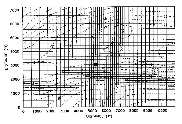
This problem demonstrates the application of stream lines with STLINE. The example application utilizes a three-dimensional flow system composed of variable thickness and variable elevation grid blocks to simulate a typical valley-fill aquifer transversed by a river. The three-dimensional, SWIFT grid, Figure 14-5, is composed of 39 x 29 x 3 blocks ranging 150 to 600 feet horizontally. Thicknesses vary from 5 to 90. Model boundary conditions include a head-dependent condition for the river and constant head conditions for the upgradient and downgradient edges of the model. Water table conditions are instituted for the top layer of the model.
To demonstrate the movement of particles,
three pumping wells are simulated causing local cones of depression. The
steady-state potentiometric surface for model layer 2 is shown in Figure
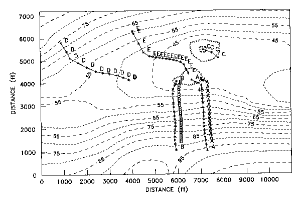
14-5. Five stream lines are evaluated (A-E). Groundwater flow converges
towards the river and the pumping wells. The streamlines are presented
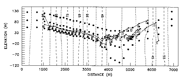
in areal and vertical sections in Figures 14-6 and 14-7. The vertical section
in Figure 14-7 is a Y-Z slice along model column 25. The block centers
of the model grid are also posted in Figure 14-7 demonstrating the variable
thicknesses. The particle location, denoted by an asterisk, is printed
at each n'th time step. Note the slower particle movement along streamline
E where the gradient is less pronounced. Streamlines A, B, and C terminate
at the pumping wells, while D and E terminate at the river, Figure 14-6.
14.7 NOTATION
Roman Symbols
S Total path length of particle p at time step n.
t Time.
Vx,Vy,Vz Components of the interstitial fluid velocities at any position (x,y,z).
V1x, V2x Velocity components at X and X + DX.
x Arithmetic average of velocities at time t and t + dt.
{Vx} Arithmetic average of velocity components at X and X + DX.
X,Y,Z System, or global, coordinates of a typical particle.
X ,Y ,Z Global coordinates of particle p at time step n.
x,y,z Grid-block, or local, coordinates
yz Asymptotic width between streamlines of injection well in a uniform flow field.
ds Incremental increase in path length occurring during dt.
dt Computational time step.
dx,dy,dz
Positional changes of a reference particle occurring
during time step dt.