The UNSWIFT program written by GeoTrans converts map files (UNIT 13) to regularly-spaced grid for SURFER using bilinear interpolation in order to create contour plots. SURFER is a registered trademark of Golden Software, Inc.
The UNSWIFT program is written in FORTRAN 77 and is currently operational on a 80386 and 80486 using the FTN77/486 compiler from the University of Salford. The program can read pressure, temperature, brine or nuclide concentration data from a SWIFT map, and prepare a grid file compatible with SURFER7.
As an alternative approach, files can be viewed directly in Groundwater Vistas. Use Plot>Import SWIFT Results..
13.1 OVERVIEW
SWIFT-2002 produces results for block-centered, variably-spaced finite difference grids. Plotting software such as SURFER7 however, work with uniformly-spaced, node-centered grids in order to contour given data. Therefore, without UNSWIFT, results from SWIFT would have to be read as "randomly-distributed" data for contouring.
Gridding randomly-distributed data is time-consuming and may introduce error. While the distribution pattern of the data points is regular and known, it cannot used by SURFER7. UNSWIFT converts this "regular" data from the model to the contouring package using bilinear interpolation. Note that it is not guaranteed to work in all situations. Sometimes, head or concentration results from a model require a more sophisticated interpolation approach.
Thus, UNSWIFT provides a convenient and accurate means to prepare contour plots by preserving the lattice nature of the map data. This is done expediently and without the introduction of erroneous contours.
An example of a SWIFT grid for a layer is shown below.
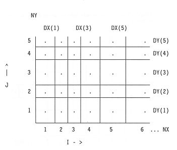
Values are calculated at block centers. The grid increments are nonuniform.
UNSWIFT converts array data from the above grid to the one shown below.
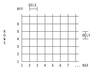
Note the changes in coordinate system and the node-centered data on the resulting grid.
The outer boundary of the resulting grid should be within the original grid, as UNSWIFT does not extrapolate beyond one grid cell. A bilinear interpolation technique is used to convert the data.
13.2 OPERATION
The operation of UNSWIFT is illustrated
below.
|
|
||
|
|
||
|
|
Variable-grid file | |
|
|
||
| unswift.ctl à |
|
|
|
|
||
|
|
Uniform grid file | |
|
|
||
|
|
STAIR.MAP is an unformatted map file generated by SWIFT. The map writing option is invoked by setting MAP > 0 in R2-13. UNSWIFT.CTL is a control file for UNSWIFT which contains information necessary for the conversion of SWIFT data. PRS_LY2.GRD is the uniform grid file generated by UNSWIFT which is ready for contouring. The uniform grid file can be in formatted or binary form.
For a typical problem with SWIFT, the control file will remain the same. The map file STAIR.MAP will change with each run. The map file may contain data for many stress periods, time steps, and layers. UNSWIFT lets one look at each array interactively and process only those needed for gridding.
13.3 INPUT DATA GUIDE FOR THE CONTROL FILE
Each record in the input data file is preceded by a record header line containing the names of variables for that record. The variable names are placed in the header line aligned with the columns where the input data is expected for the variable. For illustration, header line and sample data are shown below for Record 2.
NX NY ICODE IDEBUG FMTGRD Record
2
19 51
0 1
(8G10.0)
RECORD 1: TITLE RECORD (A60, A10)
Title record is only for documenting
the control file. It is ignored by UNSWIFT.
21-30: ICODE:
1 = formatted (as per FMTH, see cols
11-40 of this record).
41-50: ILOG: Log (base 10) transformation of variably-spaced data.
1 = yes, perform transformation.
The log transformation is appropriate
for concentration plots with data ranging in many orders.
1 = Yes, do create a grid. The program
will prompt for the file name. Usually this option is only necessary for
the first execution of UNSWIFT. For production runs, set IGRID=0.
1 = formatted (as per FMTZ, see cols.
21-40 of this record).
Specify all the parameters. Enter a
blank or a zero for IL, IR, IT, IB if window option is not used.
RECORD 6: UNIFORM GRID DESIGN
(2I10, 4E10.0)
51-60: Y0: Offset in the y-direction. Origin is at lower-left corner.
DELX is equal to 5000/(NXX-1), and likewise
DELY is equal to 4000/(NYY-1).
RECORD 7: NO-FLOW AND DRY CELL CODING (2E10.0)
SWIFT-2002 has special values meaning
no-flow and dry cells.
Provide the array DELC(NX) in the format specified in RECORD 2 parameter FMTGRD. For large grids, one may just want to transfer the grid spacing from the model input data. The parameter FMTGRD provides a flexible way of reading this data. For an areal x-y system, the DELC() corresponds to the x-grid spacing DELX() on Record R1-17 for SWIFT. Similarly the DELR() below corresponds the DELY() on Record R1-18. For Y-Z, the DELC() would correspond to DELY() and DELR() on Record 9 would correspond to DELZ().
RECORD 9: MODEL GRID SPACING in Y-DIRECTION (see FMTGRD on RECORD 1)
Similar to Record 8, provide the array DELR(NY).
13.4 RUNNING UNSWIFT
The code UNSWIFT is available for the Digital Visual Fortran. Listed below are the steps to translate a variable-spaced grid (SWIFT) to a uniformly-spaced grid (SURFER7).
2. Prepare a control file for UNSWIFT. Start with a copy of the supplied sample control file. Copy this sample file to one's control file by typing
3.2 Determine whether the window option will be used. Determine the size of the input window in distance units.
3.3 Utilize the grid spacing in the SWIFT input data file (R1-16 - 18) for Records 8 and 9 in the control file. Make sure that the record headers are still present. The input for SWIFT is list-directed.
3.4 Maximum X and Y distance is obtained by summing the grid input for SWIFT (Records 8 & 9 in UNSWIFT.) Use these numbers (if the window option is not specified) to design NXX and DELX. Similar steps should be followed for NYY and DELY.
3.5 IFMTH can be 0 or 1, as SWIFT 2.54 prepares only either formatted or binary map files. If a grid file from SWIFT output has been prepared, set IFMTH = 1, and supply a format string under FTMH.
3.6 IFMTZ should be left as zero, as it is the most efficient way of sending data to SURFER7. If it is necessary to inspect and edit certain array data, set IFMTZ=1 and supply a format such as (8G12.5) under FTMZ in Record 4.
3.7 If one is overlaying the contour line with a BLN file in SURFER, check the coordinate of the bottom-left corner of the BLN data. If it is non-zero, supply the (x,y) offset coordinates under X0 and Y0 in Record 6.
3.8 HNOFLO, HDRY, and HCUT have their
origins from earlier versions of UNSWIFT for other finite-difference codes.
Generally HNOFLO and HDRY are not used. Be careful with HCUT, especially
if the pressure at datum extend into the negative range. Also avoid negative
logs by setting HCUT to a small positive number when ILOG=1 (Record 3).
<< UNSWIFT - Version 1.4 >>
Control file name: UNSWIFT.CTL
Variable grid input file: STAIR.MAP
Time Step: 50 Time: 52.00 Data: HEAD
To process, enter uniform grid file name,
[Enter] to skip, or type END to stop: PRS_LY2.GRD
UNSWIFT reads the header record for each array in STAIR.MAP and displays it on the screen. The next prompt has three possible responses: (1) If you want to process the array, enter the name of the uniform grid file to be created, (2) if you want skip this array press [Enter] key, (3) if you want to terminate further reading of the map file and ignore this array, type END.
Time Step: 50 Time: 52.00 Data: CONC
To process, enter uniform grid file name,
[Enter] to skip, or type END to stop: CON_LY2.GRD
6. Execute SURFER7 using the uniformly-spaced file created in the previous step as the input grid (eg. CON_LY2.GRD) file for contouring.
13.5 SOME COMMENTS ON CODE IMPLEMENTATION
2. By default all non-ASCII files are "unformatted". A clever method is utilized in UNSWIFT by writing "unformatted direct access" file to appear like a "binary" file readable by SURFER7.
3. If problems arise in reading the binary map with UNSWIFT or reading the binary grid in SURFER7, change to ASCII format and examine the respective file contents for potential problems.
4. Note that the output file from UNSWIFT can be written in ASCII. This allows input into programs other than SURFER7, but note that the data have already been interpolated. Recontouring the data could produce misleading results depending on the method used. This is not true with SURFER7 because the grid input file has been written in exactly the same format that SURFER7 can read directly without recontouring. If one uses a different contouring package, the results should be checked against SURFER7 output as this is the only package supported for use with UNSWIFT.
5. It is recommended that the window option be turned OFF initially so that the entire output may be checked.
6. List-directed input is recommended for use with UNSWIFT. This allows the grid dimensions to be imported directly from the SWIFT input file. This eliminates unnecessary input errors. To instruct UNSWIFT to use list-directed input, place an asterisk (*) in the first column of the FMTGRD input (Record 2, column 41).
7. Some confusion may arise over the design of the uniformly spaced grid. In order to determine the grid spacing, decide the number of grid blocks and divide the total axis distance by this number. Please note that the number of columns and rows (NXX and NYY) should be one more than the actual number of rows and columns. This is because the numbers that are being used are the number of grid lines not blocks. Please also note that the number of grid blocks in either direction should be sufficient to provide adequate resolution of your results.
8. While UNSWIFT can be used to map a relatively coarse SWIFT map onto a more refined SURFER7 grid, use caution when interpreting the contours. For example, one can use the bilinear interpolation to UNSWIFT a 20 x 30 SWIFT map onto a 101 x 151 SURFER7 grid. This will result in "smooth" contours, but may not properly reflect the trace model results. In general, the number of increments in the variable and uniform grid should be similar.
9. Great care should be taken in constructing the control file as an incorrect entry will produce misleading results.
10. The user should verify the times at which maps are produced by SWIFT. Make sure that the input data for SWIFT (R2-12, TCHG) specifies the correct time period for mapping. Producing a map at the incorrect elapsed simulation time will cause serious problems when interpreting the output data.
Table 13-1. Example Control File Listing.
NX NY ICODE IDEBUG FMTGRD
card 2
39 29 0
1 (8E10.0)
IFMTH FMTH ILOG HCUT IGRID
card 3
1 (8E12.3) 0
0 1
IFMTZ FMTZ
card 4
1 (8E10.3)
IL IR IT IB
card 5
1 39 1 29
NXX NYY DELX DELY X0 Y0
card 6
51 31 219.0 240.0 0.0 0.0
HNFLO HDRY
card 7
0.0 0.0
DX(1) DX(2) DX(3) ... DX(i), i=1,NX
card 8
600. 600. 600. 600. 300. 300. 300. 300.
300. 300. 300. 300. 150. 150. 150. 150.
150. 150. 150. 150. 150. 150. 150. 150.
150. 150. 150. 150. 150. 300. 300. 300.
300. 300. 300. 300. 300. 600. 600.
DY(1) DY(2) DY(3) ... DY(i), i=1,NY
card 9
600. 600. 400. 400. 200. 200. 200. 200.
200. 200. 200. 200. 200. 200. 200. 200.
200. 150. 150. 150. 150. 150. 150. 150.
150. 200. 300. 400. 500.